↓ Skip to Main Content
YarkspiriFantasyArt
View, Learn, Follow
Main Navigation
Menu
Home
3D Printing
Downloadable
Reviews
Posts
Learn the basics
Mods
Review & Sponsorship
Portfolio
Portfolio
Shop
3D printing
Assets
Prints
Clothing
About
Yarkspiri
Contact Us
Info
Privacy Policy
Donate
Search for:
YarkspiriFantasyArt
View, Learn, Follow
Menu
Search for:
Off Canvas Menu
Home
3D Printing
Downloadable
Reviews
Posts
Learn the basics
Mods
Review & Sponsorship
Portfolio
Portfolio
Shop
3D printing
Assets
Prints
Clothing
About
Yarkspiri
Contact Us
Info
Privacy Policy
Donate
Tag:
3d printer
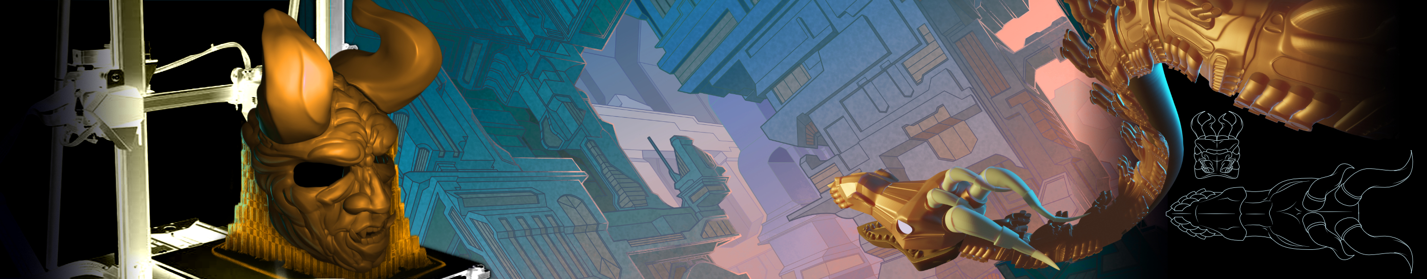
3D Printing a 15 Foot Dragon – Part 2 Modeling
3D Printing a 15 Foot Dragon – Part 1 Concept