Sla Printer – Print Flat Vs Angled
Index So you’re just learning to 3D print, but some people are telling you to print flat, while others say to print on an angle. Today we’ll go over each of these and give you information you need to make …
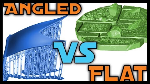
Printing angled vs flat.