CR10 V3 Fix – Cable Connection Supports

CR10 V3 Fix - Cable Connection Supports - Files in link
Video tutorial on to install replacement cables for the CR10 V3

Instructions

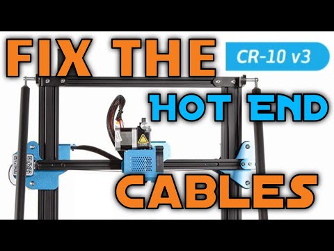
In today’s article, we’ll be addressing the issue with the cable for the hot end assembly of the CR10 V3. If any of you may have noticed, the cable connections don’t have any support and there’s a high probability that the movement will cause a failure in the connection. The cables which connect to the hub are also another potential issue since they don’t have any support either. Since I would like this machine to last as long as possible, I will be making a couple of modifications to address these issues today. As always, do these modifications at your own risk, and I’m in no way responsible for any damages which may occur.

So, like most modifications, this one went through a couple of alliterations before a final version was determined. Since the metal supports for the xz hub were the same design as the V2 model, I decided to use this to my advantage. I initially designed a mount which surrounded the cabling, however this proved both difficult to mount and risky to force the cable within the support. It was for this reason that I switched to an open design, which allowed me to use Zip ties to fasten the cables to the guide. For the hot end assembly, I knew I wanted something which simply slipped over the direct extruder motor. After taking precise measurements, I created a box like shape to encompass the motor while still keeping as much of it open to prevent overheating issues. I also designed it to wrap around the connector, so I would be able to add zip ties as well. Learning from my previous mistake, I made sure to keep an open design.

After my first test, I did discover one drawback which I hadn’t initially taken into account. While testing just how high up I could move the printer in the Z axis, I found out that my modification did remove some of it’s Z height. Wanting to reduce this drawback as much as possible, I then redesigned both the parts to help resolve this. With the new design, I was able to comfortably reach a total Z height of 395. I also made sure to better support the cables with an extra Bowden tube that I had lying around, however you may be able to use a spiral cable wrap instead should you have some available. Very important to note is the fact that you’ll have to move the support bar on the left-hand side of the machine to accommodate the increased size of the nozzle assembly. To do this, you’ll want to completely remove the top portions and bottom portions. For the bottom, you’ll want to add some washers to increase the distance at the base. You’ll then want to move the nozzle assembly as far up as you can, while also moving as far left as possible. This will make it easier to gage where to place the new connection points. In my case, I had to realign the live bolt and move the pull rod connector over so that only one support bolt was still in place. Instead of using the spacer which came for the live bolt, I removed this and replaced it with a M5x12 screw. As long as this is properly tightened, you should have no problems getting this secured in place.  Make sure to write the Z height that you have, since you’ll change the maximum Z height for your machine in your slicing program.

With this completed, it was now time to change the Z height in Cura and begin a test print. As expected, the test prints were very similar to those done previously. Since I had a 0.8 nozzle, these were the results that I ended up getting. Since I mostly use the larger machines for functional parts or prototypes, I often need these to complete at a faster rate.0.2

Although I could leave this machine without these additions, this will hopefully help increase its longevity. If you want to see how I upgraded the hot end to use an all metal one, you can see the full tutorial article at this link HERE.

Important Notes

  • Print all the parts beforehand
  • Do a test fit first
  • Write down your new maximum Z height
  • Zip ties are needed
  • one M5x12 Screw
  • Adjust Pull Rod connector + Live Bolt

Rebel Artist Christmas Auction – Ottawa Ontario Canada Region


3 Original Hand Made Pieces will be up for auction in Ottawa, Ontario Canada for 12 days only.  These rare items were made from high quality lightfast paints, graphite, pens, pencils and acid free paper.  Each item is over 15×22 inches in size and has an aged curled treatment to the surface.  Visit this link for details. 

Rebel 101.7

CR10 V3 Fix – Filament Sensor Mod

Video tutorial on how to Upgrade the Filament sensor for the CR10 V3.

Instructions

In today’s article, we’ll be covering how to go about modifying the filament run out sensor that came with the CR10V3 so that it stops catching.  As always, please do this mod at your own risk, and I’m not responsible if any damages may occur.

So as I mentioned in my previous review of the Creality CR10 V3, the sensor was very much holding back the potential for this machine. Because of the initial design for the filament intake, it caused a severe amount of friction to occur, which in some instances prevented the proper flow of filament through the nozzle. Before trying to create a new housing, I did run a test to see if I could simply replace the existing sensor with one that I had lying around, however this produced an error which prevented the printing process from starting. Instead of modifying the firmware, I decided to change the housing, which I believed to be the main cause of the issue. The electronics themselves were very well-designed, so doing this also makes this modification easier for other’s to undertake.

So the very first step was to remove the existing component and open it up to see what was inside. Luckily, this was fairly easy to accomplish because of how it was assembled on the machine. Once you remove the 4 screws holding it in place, you are immediately greeted with the electronic components. To make my life easier, I did decide to remove the filament stand, however this is not a necessary step.

Once the electronics were visible, I removed the two screws holding them in place so that I could get a better look at the housing that already existed on the machine. The first step was the remodel of the area where the sensor would be sitting, and once that portion as completed, I was then able to focus on the entryway for the filament. The issue with the stock version is that the angles were too sharp, and this was what was causing the large amount of friction. Also, the alignment was slightly off and this caused the filament to get stuck in the switch portion of the mechanism. In order to address these issues, I created a gradual entryway for the filament to the pass through and changed the point where the filament intersected with the switch. This produced a much more gradual entrance, which reduced the friction significantly.

With this out of the way, it was now time to create the connection points in which the two halves of the sensor would meet and combine to make the shell. I then added the bolt indents to further make this easier to assemble. So after a couple of prototypes, I finally had the final version that I would be installing on my machine.

IF you decide to install this one in your own machine, you’ll need to do the following. You’ll need to add the two screws to hold the switch in place, after which you’ll add the screws and bolts for the housing. In my case, I only had longer screws available, so I ended up only installing two of these across from each other. This also allowed me to place a much longer screw going in the opposite direction to attach this to the sensor mount. I added a bolt behind it just to make sure that it didn’t come off later on. With that completed, I installed it onto the machine and quickly tested it with both flexible and PLA filament. After doing my first print, I can say that it’s still working quite well, and I’m happy with the results. This was the resulting test cube, which was printed with a 0.8 nozzle and scaled to 130%.


Although this may seem like a simple mod, I found this to be one in which I appreciate the most since the friction being produced has caused my filament to break in mid-print on certain occasions. In the next article, we’ll upgrade the hot end to use an all metal hot end one for higher temperature printing.

Checklist

  • Download + Print Files
  • Remove original sensor
  • Careful take out electronics
  • Place into new housing
  • Assemble

CR10 V3 Installing BLT Touch


Instructions

In this article, we’ll be going over how to install the BLTouch on the CR10 V3 by Creality.  This review was in no way sponsored and that I had purchased the BLT with my own money at the same time as the CR10-V3 and this represents my own opinion on what I’ve experienced.

In order to do this upgrade, you’re going to need to know a couple of things. Now in most cases when you first order your machine, it came with a USB stick which had everything that you needed to get started including the firmware upgrade that you’ll need.  If you don’t have this, however, that’s fine, since it’s also readily available through the main website of Creality.com.  The firmware comes pre-compiled which is nice, however the zip file has some extra characters which prevents the operating system from recognizing the files.  So the first thing you’ll want to do is remove the extra character’s after the .zip.   At this point you can then extract the files within the folder where you’ll be treated to the instructional PDF’s as well as the firmware.

Before flashing the firmware, you’ll need to connect your computer to the 3D printer and the required cable doesn’t come with the machine, so you’ll need to obtain one prior to installation.  Furthermore, you’ll want to make sure that your chosen slicer software is closed was well as any other flashing software such as Xloader, arduino or pronterface.  In order to do this upgrade, you will need to use the included Creality Slicer, since simply inserting an SD card with the firmware will not work or using Cura and Xloader.  This software is also available through the main website.  While you might be able to use a custom bootloader, this wasn’t something that was tested at the time, since the upgrade worked with the included software.  

Once you have the Creality Slicer open, you’ll need to make the following changes. Go to File +Preferences and change the printer window type to “Pronterface UI” then select “Ok”.  Then go to File + Machine Settings and change the Serial Port to “COM3” then set the baudrate to, 115200 at which point you can select “Ok”.  Then go to “Machine“, install custom firmware and navigate to the BLT touch firmware that you intend to install.  In my case, I renamed the file, however it will most likely be called CR-10 V2TF1.1.6.0BLTouchV3.1. Give the machine a little time to finish the upload, at which point you’re ready to do the rest of the installation process.  

To begin, we no longer require the Z axis End stop, so for this reason we’re going to remove this so that it doesn’t interfere.  The next stage is to installation the BLT touch itself.  You’ll want to put the first two screws going upwards from the bottom of the sensor on the side which you see the 3 holes.  The Only two holes will have screws for them.  Make sure to add the connector cable to the BLT, since it will be difficult to access this once it’s installed fully.  After, you can then install the remainder two screws to the appropriate location on the nozzle housing.  Remove the XE Transfer Interface Housing so that you have access to the female pin header and attach the connector to it.  You can then re attach the housing to complete the assembly.  

The next stage is to set up the BLT touch levelling, and first we will do a basic bed levelling to determine the low and high points on the machine.  To do this, go to “Prepare” + “Bed levelling” and allow the machine to complete the probing.  We now need to set up the Z offset, which is currently set higher to ensure that the bed isn’t damaged.  Go to “Prepare” + “Move Axis” + “Move Z” + “Move 10 mm” where you’ll set this to 00.00.  Then go to Move 1 mm and lower this the first couple of increments but not too far otherwise you’ll hit the bed.  You’ll then want to move it 0.1 mm at a time to get it to the appropriate height.  Make sure to write down this value, since you’ll need this latter.  You can use a piece of paper to help ensure that you have the proper distance if that’s what you’re currently used to using.  Go back up the menu hierarchy and go to “Control” + “initialize EEPROM” where once you enter this menu you’ll get a warning beep.  Go to the “Motion” + “Z Offset” and set the number that you wrote down here.  Back one menu and choose “Store Settings“, at which point the machine will beep another warning.  Navigate out to the main menu, where you can then start your first test print. I’m using a model which was created by   Bnimon on Thingiverse.  Since they created a file for the different nozzle widths and I had changed mine to a 0.8.  I will be including the link in the description below if you would like to use this yourself.

Make sure to keep the wire slack, otherwise the connector will get removed while printing.  With all these steps completed it was now time to do a test print and these were the results.  For any of you who’ve been doing 3D printing for a while now, you’ll have an appreciation as to how long it can take to clean up a model such as this.  In this case it took well over an hour just to remove the supports and I ended up getting large chucks half across my room.  So ya, I’d highly recommend some eye protection depending on the filament that you’re using and unless you have very calloused hands you may also want to use gloves.  Over all, however, the final model turned out pretty good considering it was printed with a 0.8 nozzle and 0.5 layer height.

So was this mod worth the effort.  In my case I would say that it was since I rarely swap out my nozzle, however if you swap out your nozzle more often than this may not be faster than simply hand levelling the bed, although it is more accurate.  So like most cases, it will depend on your use case, but I would suggest adding this if you have the opportunity since it is quite useful.

Exit mobile version