Sla Printer – Print Flat Vs Angled

Index

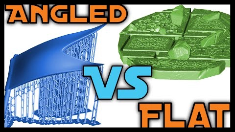
So you’re just learning to 3D print, but some people are telling you to print flat, while others say to print on an angle. Today we’ll go over each of these and give you information you need to make your decision.

As discussed in the previous video, the orientation of the model plays a large role in both the type of supports that are needed and their number, but there are two main types to keep in mind. Some models can be placed flat on the build plate, while other’s must be printed at an angle. There are several main factors that will determine which technique is more appropriate to that specific model. These include the amount of surface area, size and shape.

 While the size and the surface area may be closely related, they do represent two different criteria. The amount of surface area is generally determined by the flat surface that will be placed on the build plate, along with whether the model can be hollowed out while preserving the desired physical properties. For this character, it has quite a bit of surface area and would have created a lot of suction forces to contend with, therefore it was oriented to reduce the amount of suction and was also hallowed out.

The size is the overall scale that the print will printed at, and this does affect the amount of surface area. For smaller sized prints, these often don’t include very thick portions and rarely need to be hollowed out as a result. Smaller prints, will generally have to deal with less overall suction forces, allowing these to be printed flat if the shape allows for this. This Happy Tooth design didn’t require any supports whatsoever because of the modelled shape along with flat base. Since it was printed at a smaller scale, the suction forces were limited and didn’t pose a problem.

The shape normally includes detailed elements, which can have overhanging areas that may need additional supports in order to print properly. Models, such as miniatures, will often contain multiple overhangs and islands that need additional supports. In those cases, it’s quite common to print these on an angle and lifted from the build the plate. Functional or mechanical parts may not require as many supports, if any, in order to print successfully. The functional 3D prints can often benefit from being printed flat, should the overall surface area be limited. For these wolverine blades, I created custom supports that would easily be sawed off later, while making sure to orient the model upwards to reduce the amount of suction forces. In this case, I was able to print the model flat with a limited number of additional supports.

A big factor, to also consider, is the print bed adhesion. This portion is quite often overlooked by new user’s but plays a crucial role when printing an object flat. Ensuring a properly levelled bed is crucial for any success and should be the first thing a user checks. Items such as flex build plates can often make this task more difficult because of the small amount of flexing that occurs along the surface every time the build plate lifts away from the FEP sheet. There’s generally two ways to mitigate those issues. The first is to adjust first layer exposure settings. Increasing the first layer exposure will increase the adhesion to the build plate surface and should be the first approach to take. The second is to sand the surface periodically with 250 to 350 grit sandpaper, making sure to maintain a flat surface. Prior to attaching a flex build plate, I always recommend that you take a look at what you intend to use that machine for. If you’re going to use the printer for miniatures, then a flex build plate is often beneficial. If you plan to use the machine in a setting where tolerances are of the upmost impotence or for a variety of projects, it might be better to leave the plat as is for now.

With a better understanding of how and when to print your models flat vs angled, you probably have questions about setting up your supports, so we’ll go over the basics in this video here.

Notes

  • Printed flat or angled
  • Two factors = Size + Surface
  • Smaller prints = Less suction forces + less surface area
  • Greater suction forces = Greater print bed adhesion
  • Flex build plate = Lower print bed adhesion (adjustment might have to be made)

Recommend Articles

SLA Printer – Advance Resin Support For Production Runs

Creating supports for products.

Professional Support Design

If you’ve been 3D printing for a while now, you may want to look into creating your own supports native within your modelling software.

This type of workflow is great for instances where you’re working with similar products that have minor changes to them rather than individually unique items. Within a production setting, this workflow can become a powerful asset once you’ve passed the initial development stages. While it is true it can take a while in the beginning, often this makes for a more efficient workflow process for post-processing, and finishing work.

The easiest way to do this is to take information which was established from the automated supports, and carry these over to the 3D software. Before doing anything, you’ll need to ensure your 3D model is at the proper scale within the software, since this will make the values more accurate. The main information you’ll need for this is your layer printing height, initial bottom layer count, upper diameter for your connection point as well as the middle diameter for the pillars. I’ll be using Blender, which is a free open source software, but this information will apply to anything similar, whether it be for animation or CAD.

My custom keycap designs are a great example of this implementation, since they were all very similar and only contained slight modifications. For these models, I created a rectangle that was the total thickness of my initial bottom layers. Using my upper diameter information, I created supports which were this thickness, making sure to place these along the base of the model. It’s very important that, while doing this, to include gaps that will act as drainage holes. These gaps will help relieve any pressure build up that can be created due to the suction forces. Once printed, all of these supports could easily be removed with the use of a simple prying tool or sanded off until I reached the base of the key-caps. These were the final results that I ended up with, and they worked like a charm.

A larger scale example was the wolverine claws that I designed for a client. In this case, I created a base that would be easily to cut off after the print completed. This saved me a bunch of time in is my post-processing, since I only needed to really worry about the softening of the one edge of the model. Now although I did sand everything to ensure that they weren’t any layer lines, if this was for a rush project I still had the option of going straight to the painting process if I needed to. So, although it normally takes quite a few test prints to ensure that such supports will be successful, this is where utilizing some of the built-in slicer features can be helpful. In Chitubox and other slicers, often problem areas will be highlighted, so previewing the model first will give you a better idea of where to place such supports.

Another added benefit of doing this workflow, is that it can help influence the model design to help ensure that minimal supports are needed to begin with. My baby ghost design is another great example where this is the case. Compared to the original design, which would have required much more supports, the final versions require little to none as a result of how the mesh was modelled.

A lot of the finished products I make such as my collectors coins, necklaces and rings all use these techniques, and it greatly reduces the amount of time that I personally spend on post-processing. During a tight deadline, this means that I can normally finish a product within a couple of hours to within a day after the printing has completed. But what about the controversy of printing your models flat on the build plate? Well, we’ll go over that in an upcoming video.

Important Notes

  • Ensure proper scale
  • Layer printing height x initial bottom layers
  • Pillar upper diameter (min support thickness)
  • Pillar middle diameter (max thickness for supports reinforcements)
  • Preview highlighted areas in slicer
  • Design model to require little to no supports

Additional Resources

Sla Printer – Creating Perfect Resin Supports

How to set up proper SLA resin supports for a successful resin print.

Index

Setting Up Support Settings

In today’s article, we will focus on customizing our settings to get the best results from our resin prints.

Orientation, size and surface area all play an important role in a successful print, but each of these often depend on the type of model you have and the resin being used. It’s very important to first establish proper exposure settings for the machine, since this affect the results of the calibration. I personally prefer to use Photonsters Validation Matrix 2 for my preliminary calibration, and I will include a link in the description below. It prints quite quickly and allows me to get results fast. If at all possible, it’s generally recommended to print with a colour that’s easily readable, since this makes it easy to gage the results. I generally always start with the manufacturer’s recommended settings, then incrementally increase these or decrease them until these two points are just barely touching. I will also aim to make sure that as many of these lines are printed as possible.

Some slicer’s offer a variety of saved settings for different use cases, and these will be important to set up properly before even adding them to your model. In Chitubox for instance, you can choose between your light, medium and heavy supports and these can vary quite a bit depending on the use case. In order to determine what settings to actually use, especially for the model contact points, you could do it the long way or use a model that’s similar to Amerlabs. This model is great for figuring out the support thickness for the smallest of supports, as well as their connection lengths. Amerlabs has included a great guide on how to use their calibration test, so I’ll include this link as well. Once you’ve figured out which dimensions worked best for your specific resin. You can then begin creating your custom support settings. Seeing as the most difficult settings tend to be for small miniatures, we’re going to focus on these for now.

To start things off, we’ll adjust the bottom exposure number, since this is quite often is too high. I’ve found that in most cases I only need to have one to two bottom layers, so long as I increase the bottom layer exposure time. To find out what this should be set to, you’re going to refer to that initial test where you printed the validation matrix. I normally add between 5 and 10 seconds to this initial bottom exposure time to help ensure proper adhesion. For the medium and heavy support settings, I’ll normally go with the standard recommendations since they require more rigidity.

We’re then going to take the number for the layer height and use this to calculate the platform touch shape thickness. For small prints this normally only needs to be a 1 layer, but for larger one’s I’ll use 2 to 3 times that initial thickness (layer height x bottom layer count). Generally, the heavier the support that I need, the thicker I’ll make this, so it remains rigid enough not to bend or break. You can see in this example the differences between my different types of support.

The connection point’s Upper diameter will depend on the results of the Amerlab’s test. I normally go slightly higher than the first successful pillar dimension, which is between 0.1 to 0.5 mm. The lower diameter for the connection point will be the same as the thickness of the pillar, however some users choose to reduce this number. I normally set the connection length just under the first successful test, just to be safe.

The pillar shapes have to support the model and remain rigid enough not to flex while printing, so in this case I normally air on the side of caution. I normally go slightly above double the thickness when compared to the “Upper diameter”. This helps ensure that the pillar will have a lower likelihood of flexing during the raising and lowering of the build plate. When setting up my heavy supports, I’ll set these fairly large, since I normally use those when I’m printing props. Models such as those tend to be quite heavy, and the last thing I want is for a print to fail or fall off.

When using automated supports, I’ll normally have these set to above 90% with an angle percentage of 35%. With the basic settings for your supports, it’s now time to implement these with your first prints, and you can see that process here.

Links to Calibration Files

Resources

Sla Printer – What are resin supports

How it all Works

If you’re new or interesting in starting 3D printing, you’ve probably heard that you needed to support your resins prints. But what is this, and how is it important? Today’s we’ll explain this core principle along with how it all works.

Resin prints are created using multiple layers of exposed resin and while this process can be relatively fast when compared to other’s, it does have some important considerations. Everything needs to be connected to the build plate in order for a successfully 3D print to occur. This is mainly due to the fact that the resin is only partially cured, requiring it to be attached to the remaining structure to prevent it from becoming stuck to the FEP sheet or floating freely within the vat. These stuck portions and floating particles can cause serious damage to the LCD screen if not taken care of. In a lot of cases, this will require their removal prior to continuing onto the next print, which results in lost resin as well as time.

Any portions of the print which aren’t connected to the remaining print structure or build plate are known as Islands. Examples of this can be clearly seen in the photon validator or on the layer preview for Chitubox. In this case, I’m showing you a supported and unsupported version, so you can get a better idea of what to look for.

When a print is completed, the material is only partially cured to ensure that all the details are present and not washed out from overexposure. This will often mean that it’s more flexible, therefore these regions need more support to prevent them from flexing or distorting. Portions which hang or extend outwards are known as overhangs. Take special care when dealing with these regions, since they will often need quite a few supports to ensure that the structure prints properly.

Another big consideration is that the print needs enough supports to keep it attached to the build plate. The main reason for this is that a large amount of suction is created when the FEP sheet separates from the build plate. My video on “How an SLA printer works” goes through this in more detail, but you need to know that adding supports is intended to overcome those forces. How a user orients their print, will often affect how many supports are needed, as well as the amount of suction that created within regions of the prints. In these two examples, there’s a large amount of suction created on one version while the second one has a lot less, which is due to their orientations.

The weight of the printed object will also contribute to the number and type of supports which are needed for a given 3d print. Since prints are done upside down, they have to contend with gravity as much as they do with the suction forces. This is often the leading reason why a print will be hallowed out prior to being sent to the printer. By removing any excessive or unwanted resin in the printing process, a user can save on material while maintaining great overall results.

Now that you understand the importance of supports in resin printing, we’ll go over how to set up basic supports.

Important Notes

  • Overhangs
  • Islands
  • Orientation
  • Weight

Recommended Articles

Exit mobile version